Portfolio
Meadowlark Mini Flight Computer
After finishing the
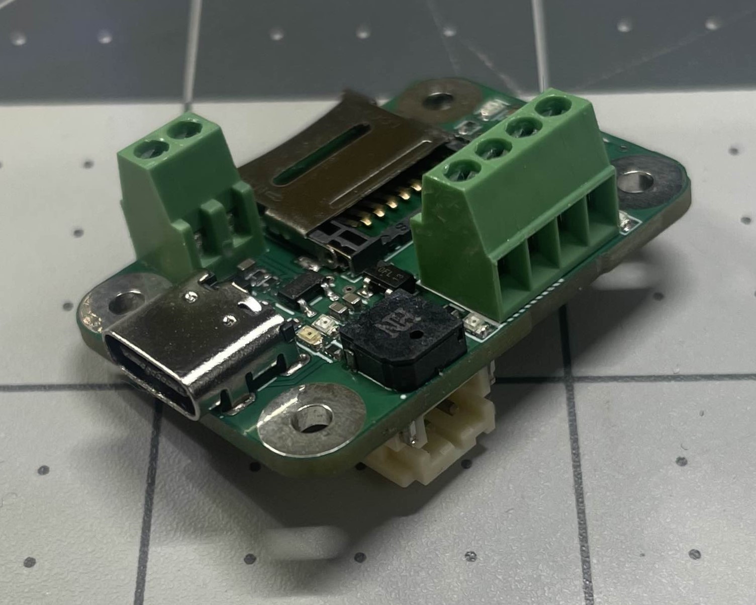
Spaceport America Cup rocketry competition, I was inspired to obtain my Level 2 high power rocket certification. To accomplish that goal I needed a flight computer. After some research I decided to build one myself. The flight computer I created aims to deliver low-cost dual deploy functionality. The controller is equiped with dual pyro channels, buzzer, MicroSD for logging, altimeter, gyroscope, and accelerometer, which fits in a 29mm chassis for H class motors.
Experimental Sounding Rocketry Association (ESRA) Team
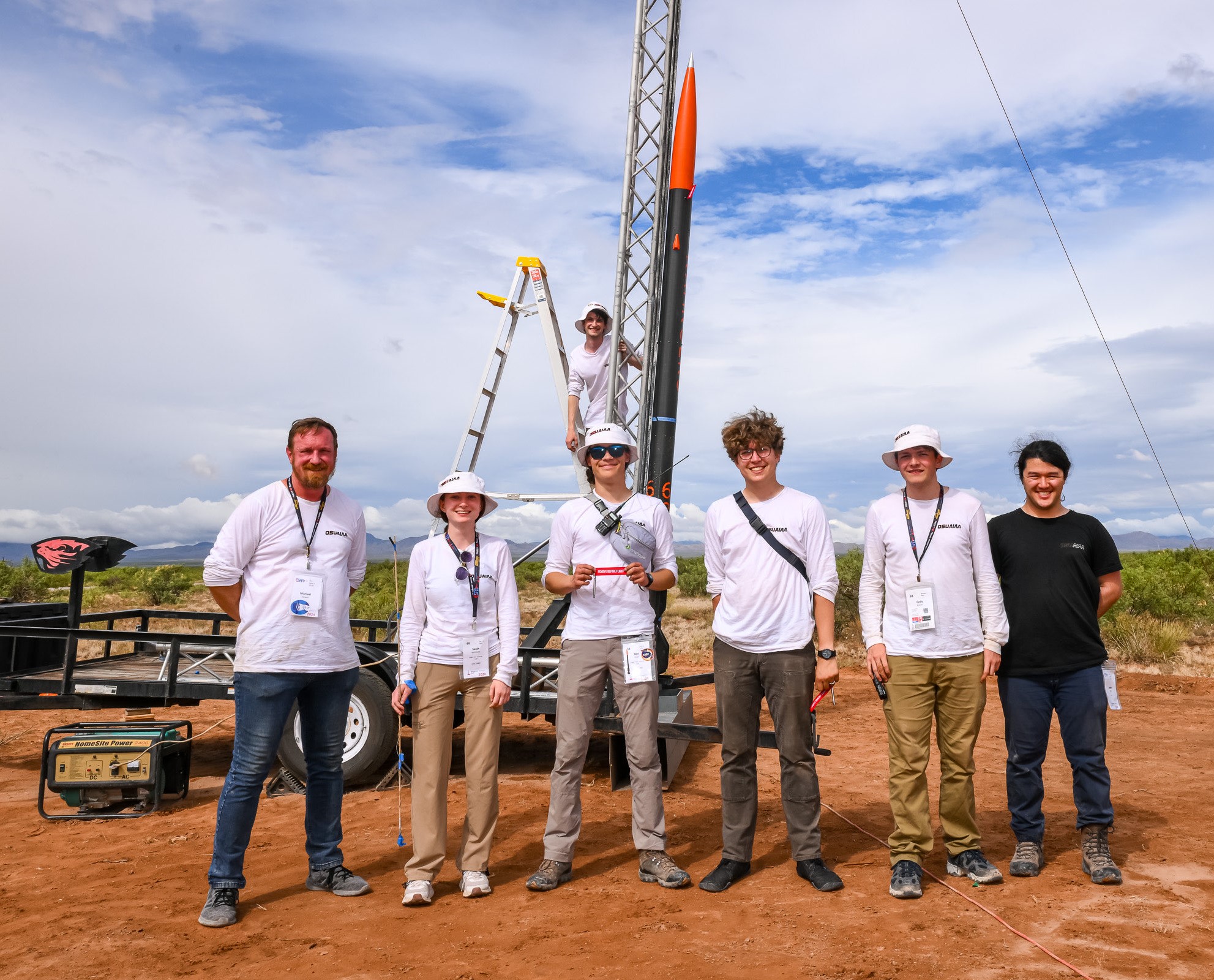
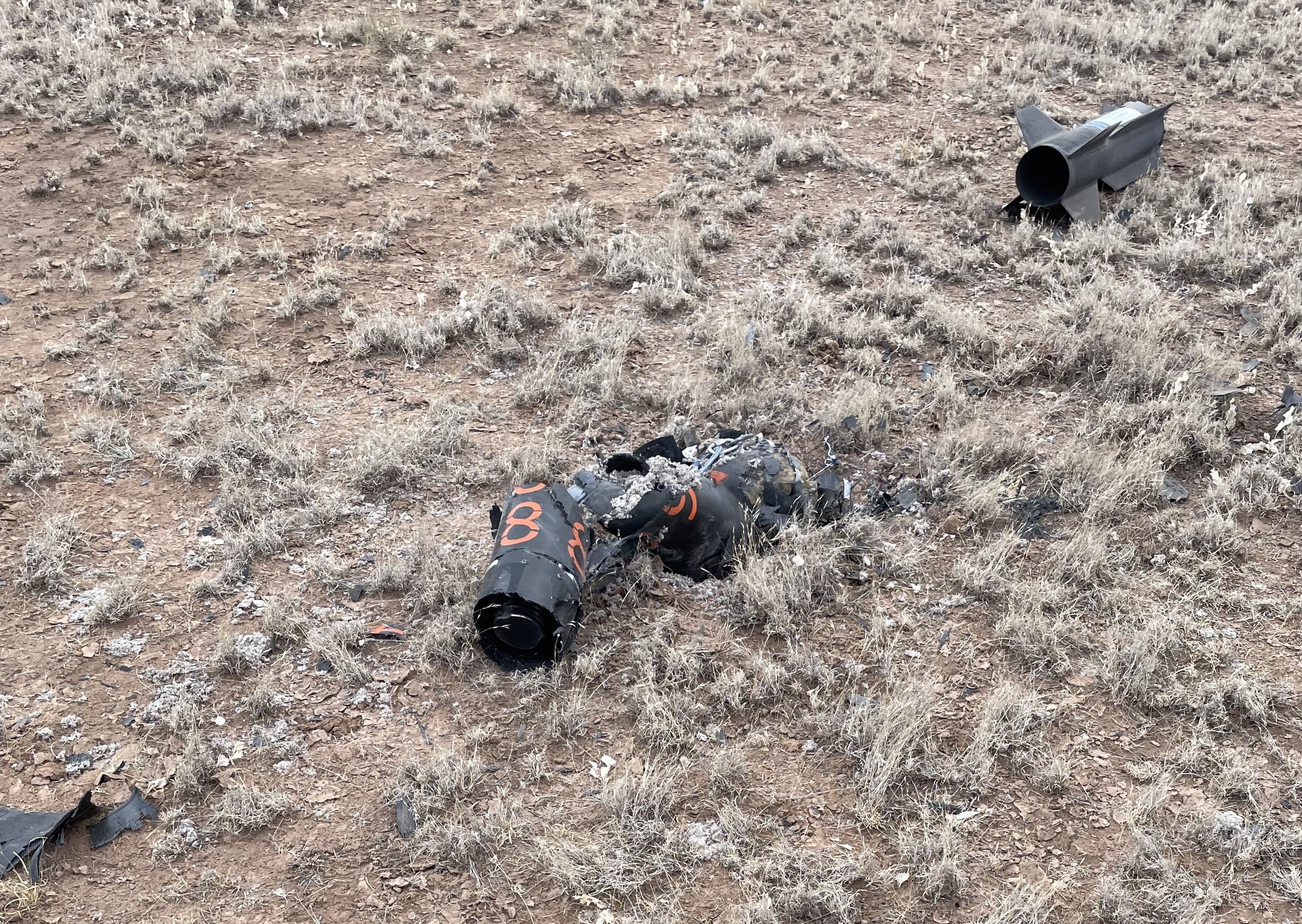
In September 2023, the President of Oregon State University’s (OSU) American Institute of Aeronautics and Astronautics (AIAA) program reached out and asked me to form a new rocketry team. I attended numerous club recruiting events and presented at the AIAA Fall general body meeting to recruit a diverse team of undergraduates. By December our team was awarded an OSGC grant and accepted to compete at the Experimental Sounding Rocketry Association’s (ESRA) Spaceport America Cup. As Team Captain, I secured space to work in, materials, and supplies. Over the next four months our team designed, prototyped, tested, and launched our rocket for the first time in Brothers, Oregon. The rocket was successfully recovered with only minor damage to the forward section of the rocket due to a parachute failure. The rocket needed to be shortened by a foot to remove the damage. With the change to the lenght of the rocket strakes (long fins above our main fins) were added to increase stability. During static testing the rocket motor experienced an explosive catostrophic failure so were unable to perform a second flight prior to competition.

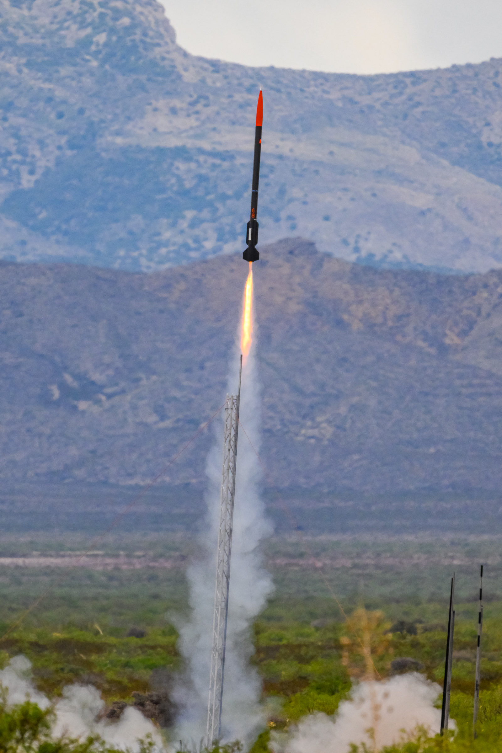
During the flight at Spaceport America, the rocket lost the motor due to a gas leak. The rocket flew to only 5000ft before returning to the ground ballistic. While this was an suboptimal outcome, I could not be more proud the team and everything we accomplished. Our technical report scored well and our engineering was sound. I have immense gratitude for everyone who spent weekends and late nights, I couldn't have asked for a better team. Everyone's dedication and perseverance was inspiring.
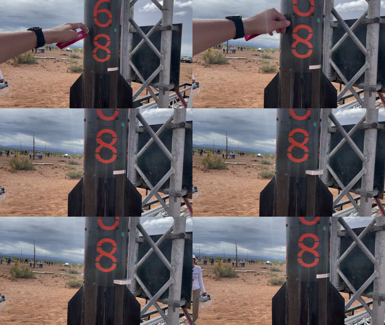
Video credit: Cody Eutsler
BEAVS Air Brakes
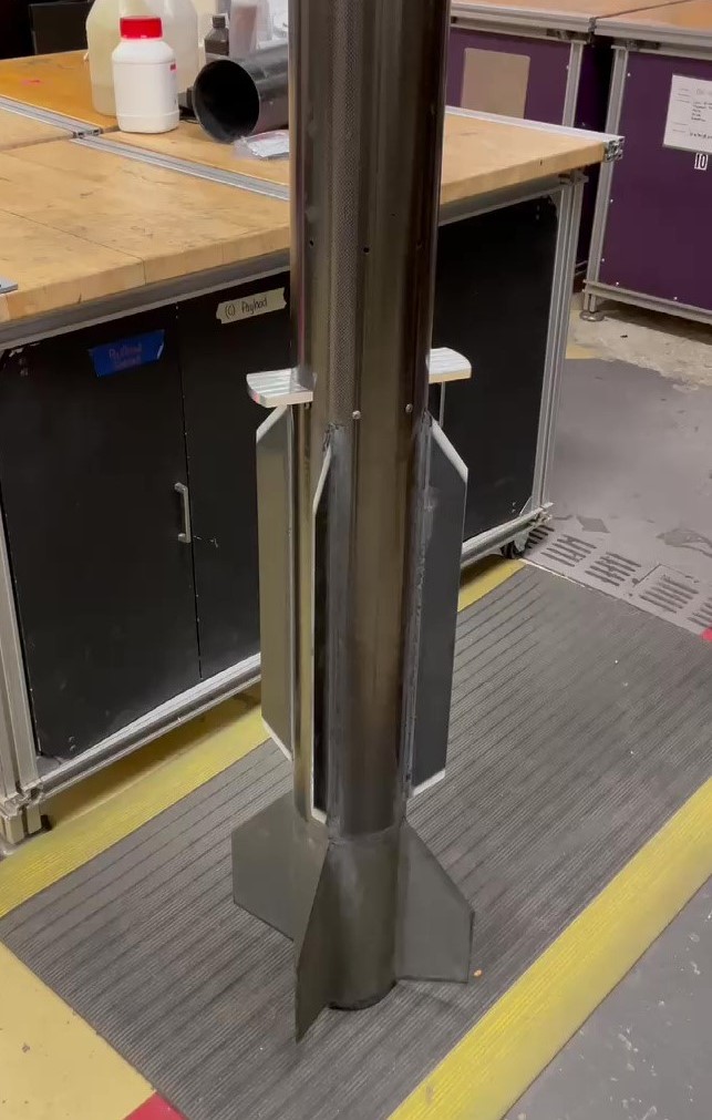
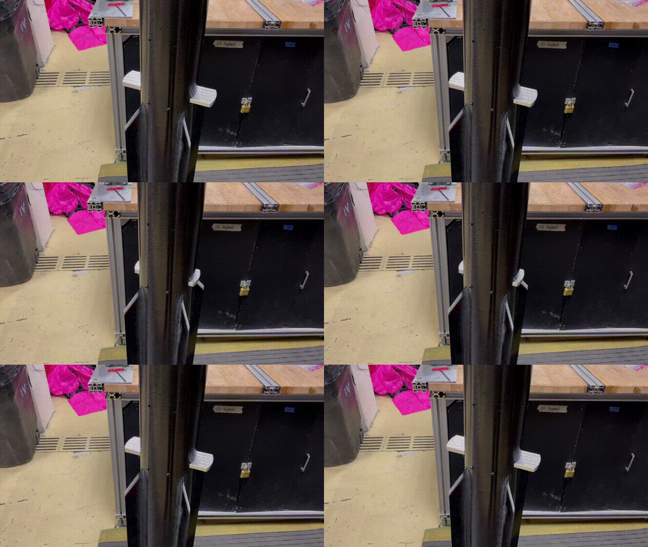
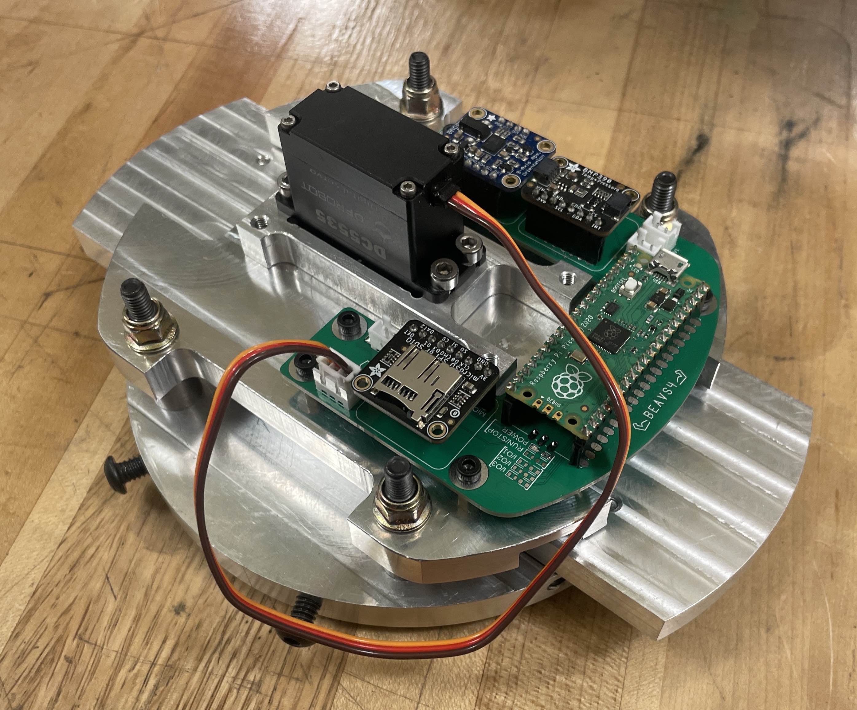
For my senior capstone project at Oregon State University, I brought back the Blade Extending Apogee Variance System (BEAVS) research project. I aimed to make the largest, most advanced air brakes at Oregon State to date. The system is actuated by a single high torque servo motor with a rack and pinion to control the blades. The controller is run off a RP2040 with an altimeter and 9-axis inertial measurement unit. The parts were machined from 7075 aircraft grade aluminum with the total system weighing 1.6kg (hardware, electronics, and batteries). The blades sit flush with the 158.75mm (6.25") airframe and are able to extend 70mm (2.76") out each side of the airframe. The BEAVS4 system flew at Spaceport America however was unable to activate due to a motor failure early in flight.
Rocket Launch Boxes
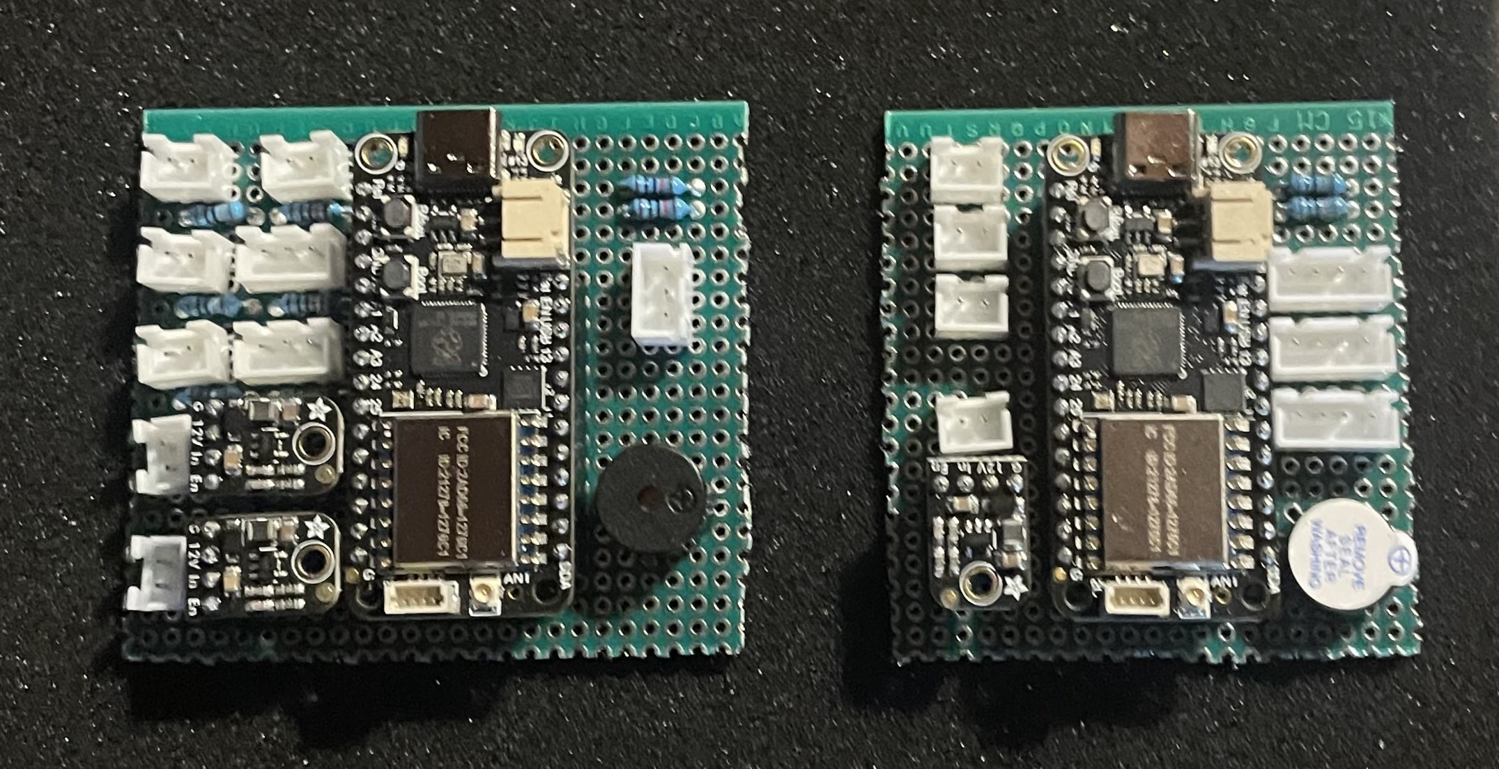
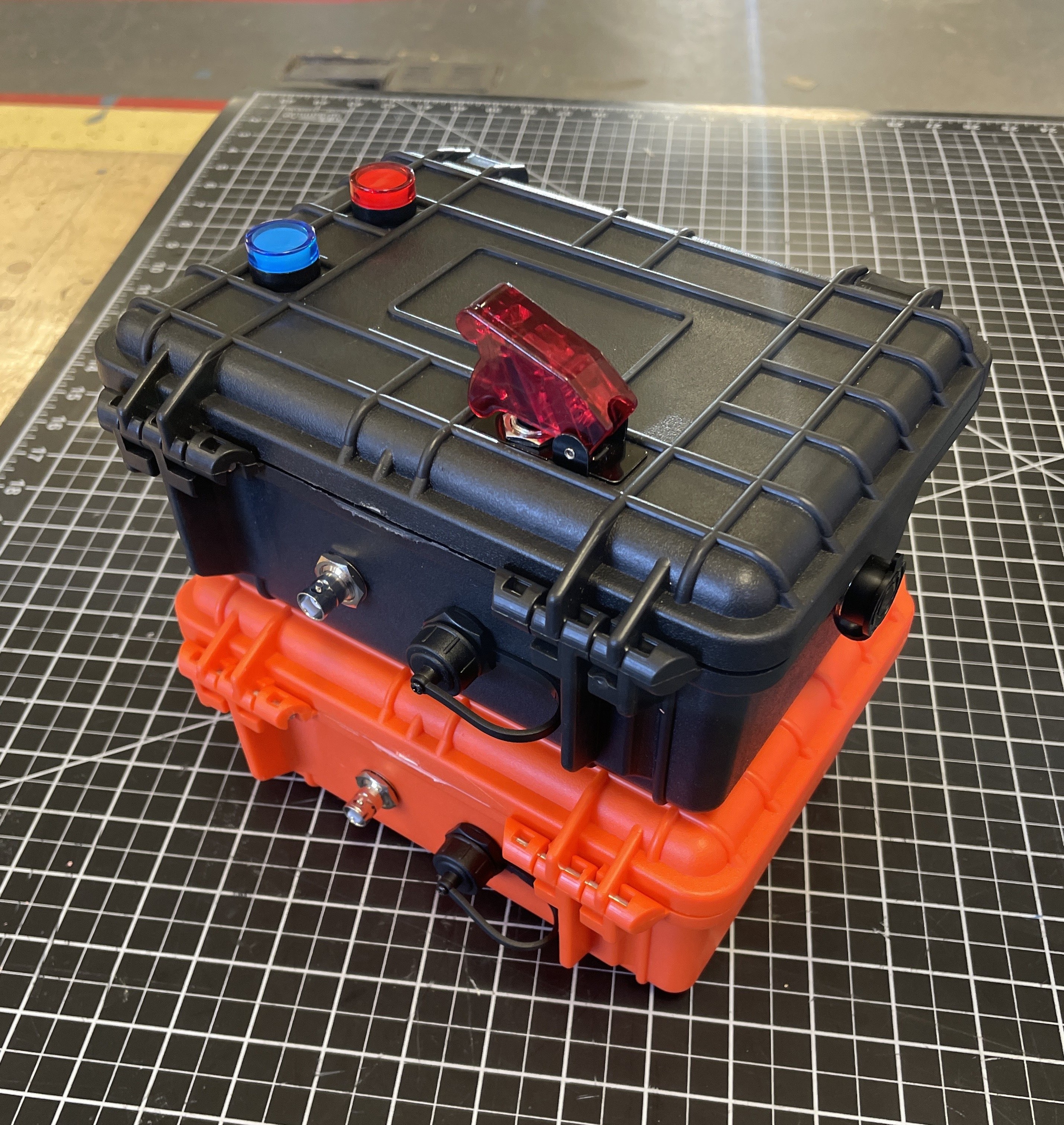
After our first launch in Brothers, Oregon, our team decided we needed a more reliable and up to date launch control system. I built a new launch control system that followed OROC and Tripoli guidelines to ensure that it met all safety standards.
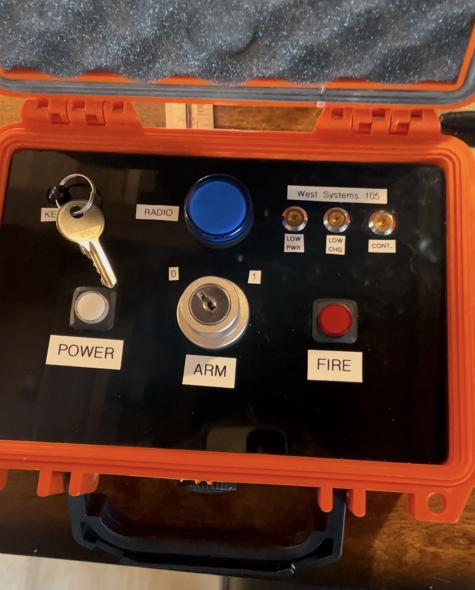
Each box in the system is powered by an RP2040 equipped with LoRa radios at 933MHz and is equipped with BNC quick-connects for antennas and USB-C for charging and debug. They have the same radio indicators and buzzers for visual and audio cues which are synced at all times. The field box has a removable 10ft cable with clips to connect to the ignitor. The system is mechanically disconnected until it is armed and fired remotely. With the box being turned on before evacuating the pad. The control box is able to see the status of the field box remotely. It is able to arm the field box with a key and fire with a button controlling two separate relays in the field box. With indicators for continuity in case of a miss-fire.
If this project continues the hand-wired boards need to be replaced with proper PCBs for long term reliablity.
High Power Rocketry L1 Certification
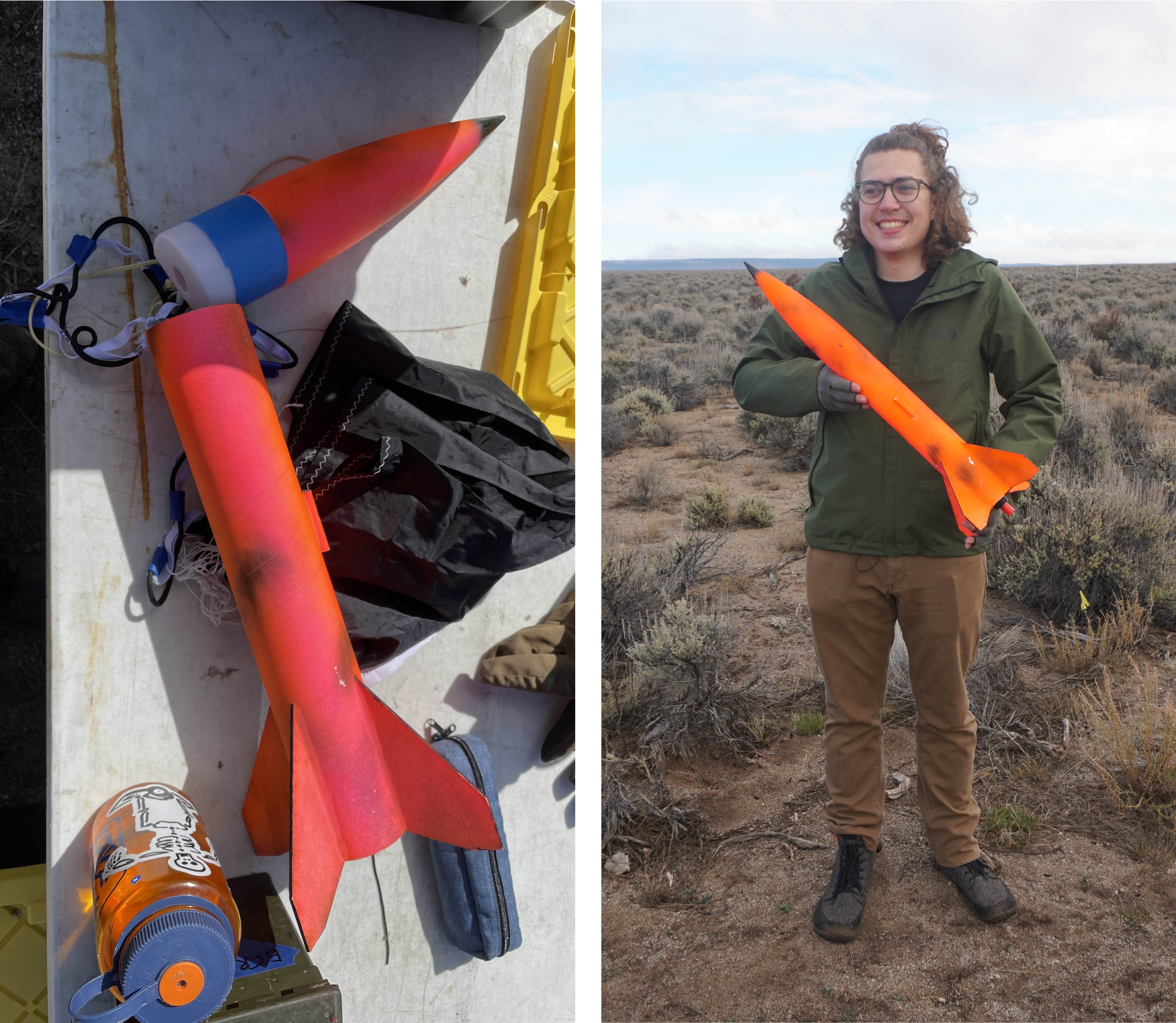
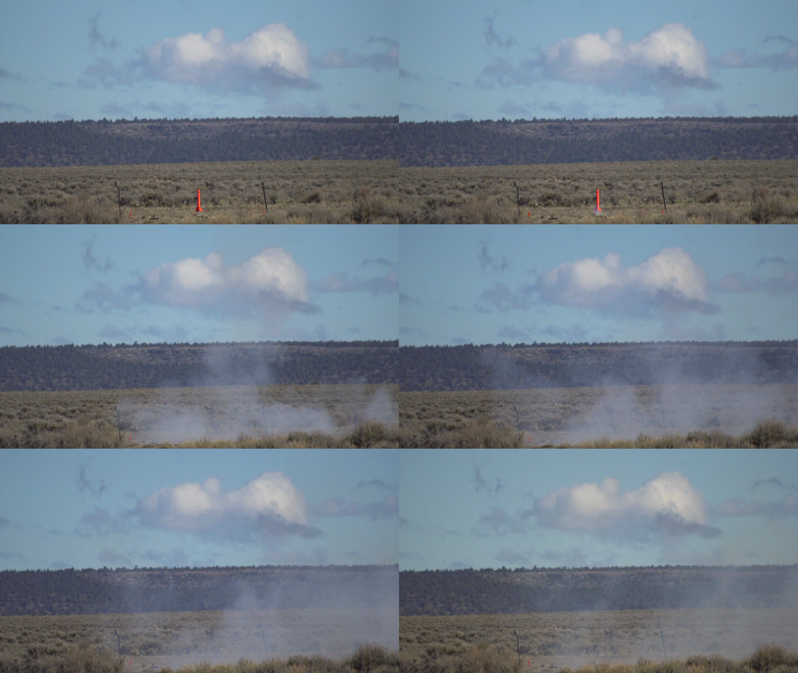
Part of my role as Team Captain was transporting the rocket motors. The university insurance required that we get high power certified. I was L1 certified by NAR in Brothers, Oregon with a successful flight of my Balsa Rocket on an H class motor.
Burl Mini Air Monitor
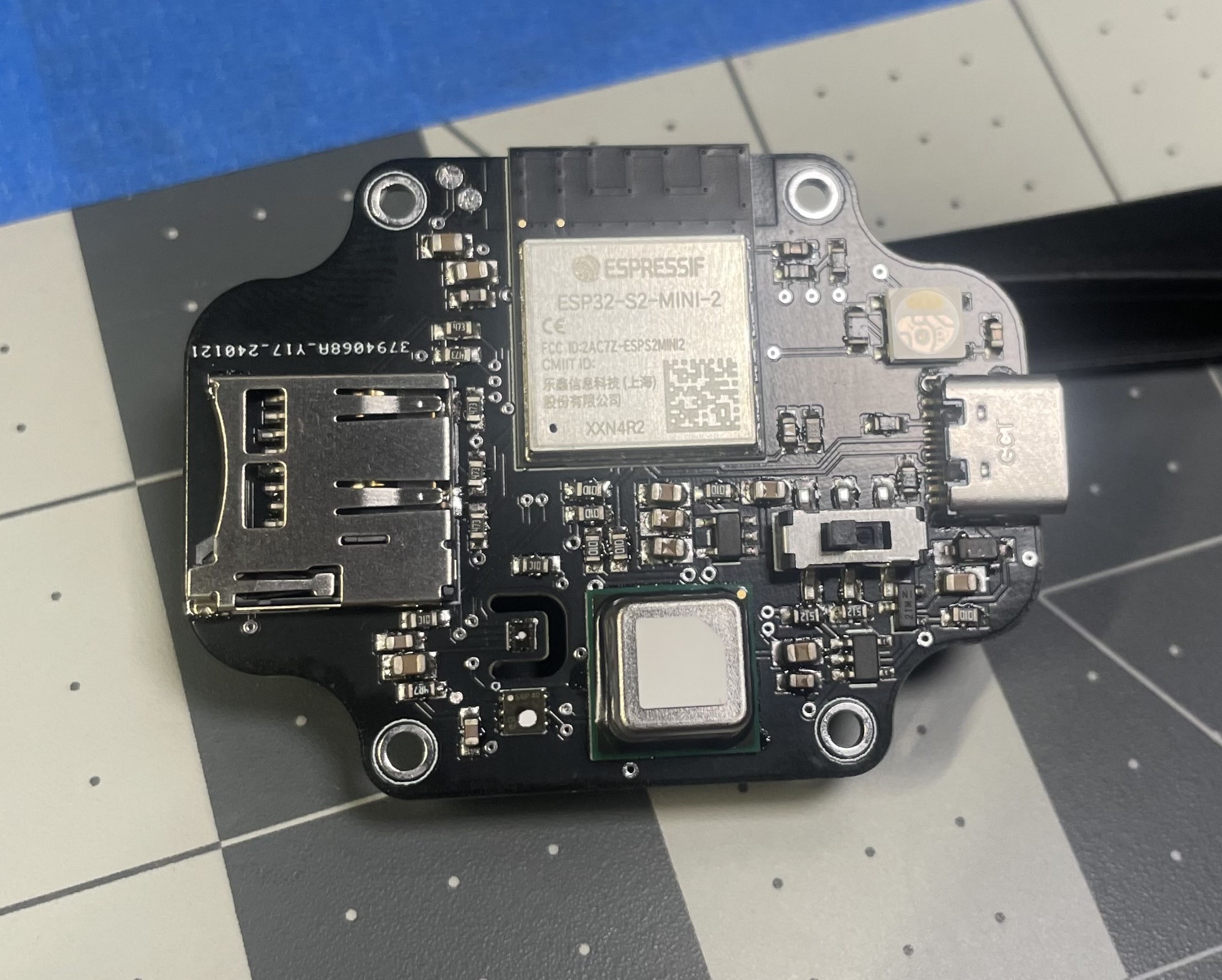
The goal of the project was to deliver a Wi-Fi capable air sensing module able to monitor gas concentrations and air quality for uses in indoor farming and air monitoring. I designed it have competitive functionality with commercial options while adding modern, user focused features. This involved adding USB-C for power and debugging, MicroSD for data logging and configuration, and user swapable battery.
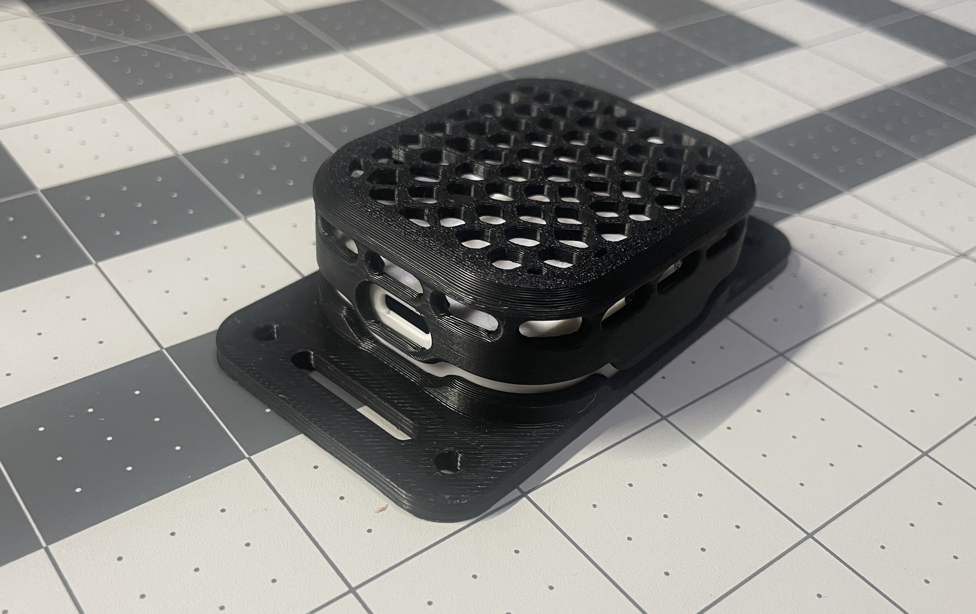
I focused on the user experience and making a polished product, while also trying to minimize the number of parts onboard. To keep the system safe, the enclosure lid snaps in place covering the sensors and MicroSD slot from damage during operation. The base is equipped with mounting holes and slots for various mounting options.
BB-8 Robot
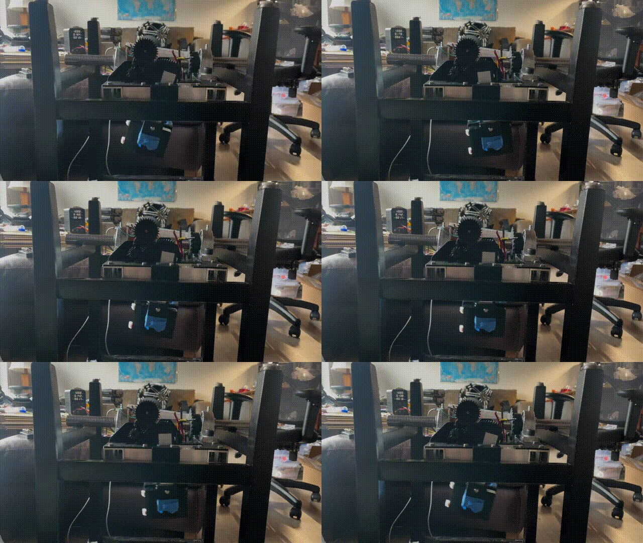
I initiated this project for fun. I was curious how the robots used in filming the movies worked inside. After doing some research I found photos and videos from the engineers showing how the full scale robot worked. Using the photos and videos of the robot in action I made a design for how it worked internally. Part of my design strategy was to start simple and built a test platform to test the movement of the ball first. Then add the head and puppeteering functionality in a different revision.
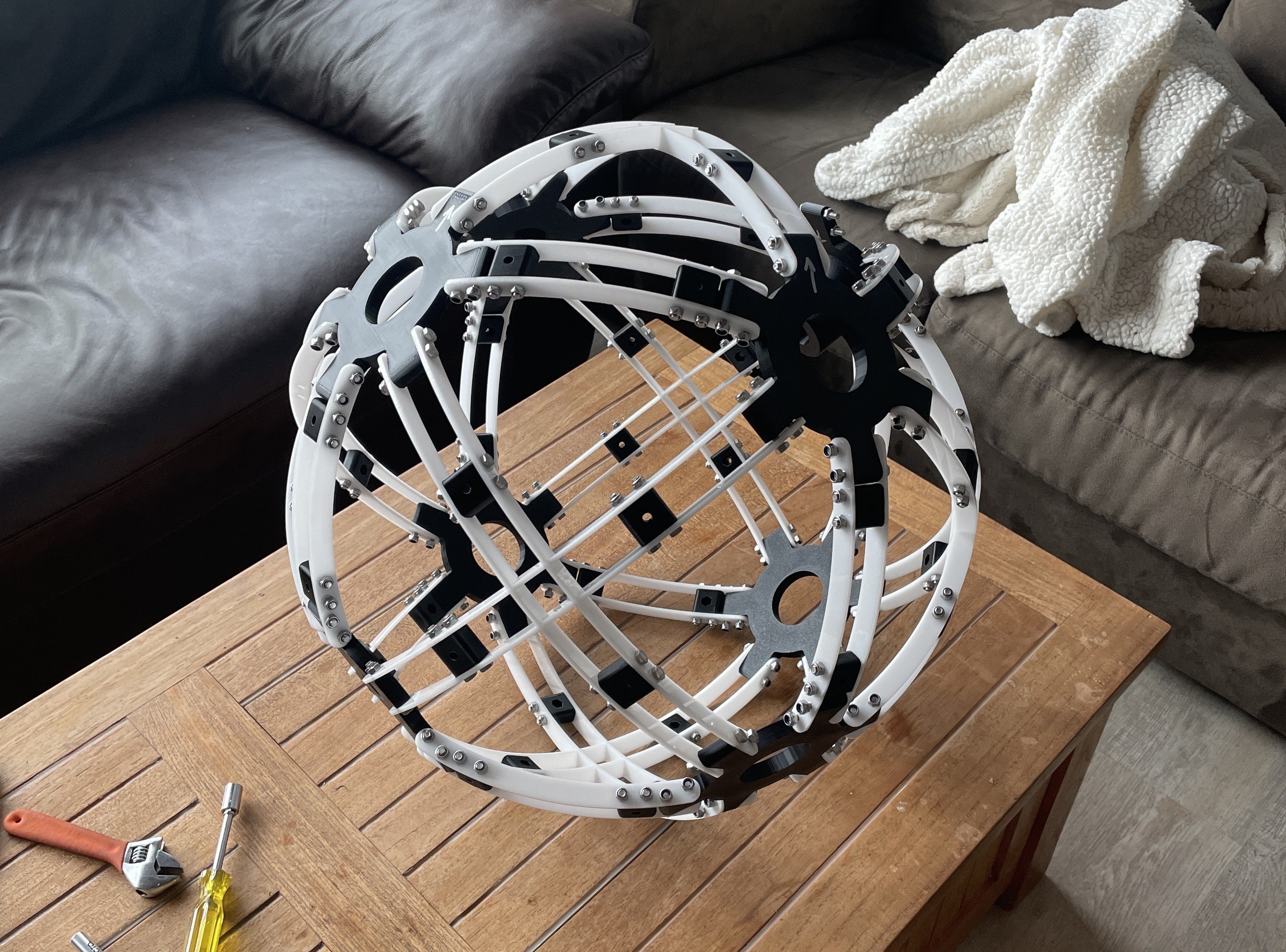
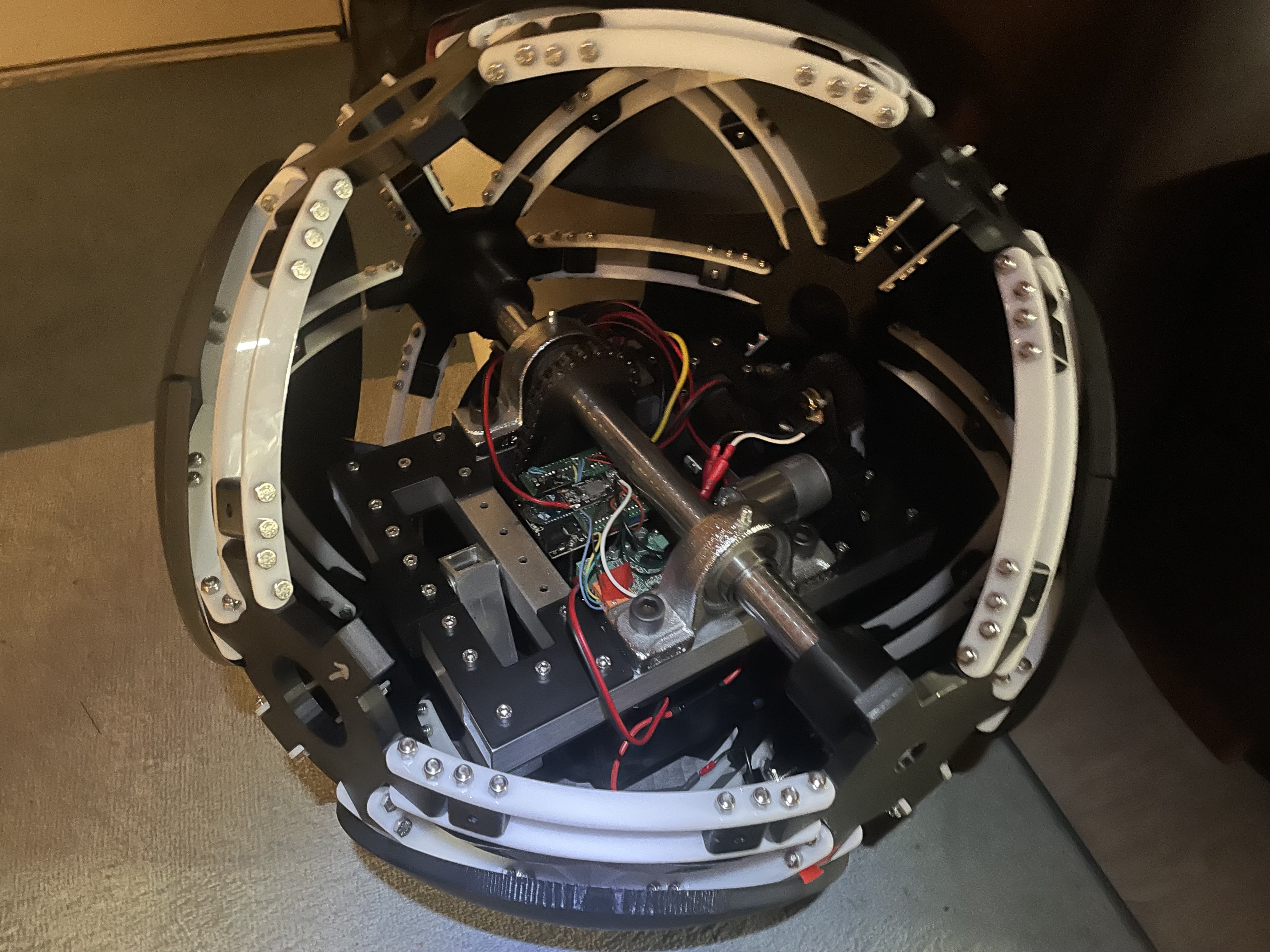
Working on a budget I assembled the inner frame from laser cut acrylic pieces with a 3D printed outer shell; with the exterior shell cut into 14 panels. The robot hangs from the drive shaft and uses a counter weight to tilt the ball side to side. To save on buying a counter weight I used the lead-acid battery powering the robot as the counter weight. To drive the ball, I used a 100:1 vex gearbox and motor with a bike chain and another 4:1 ratio. To control the tilt I used some random 12V motor and a 90 degree potentiometer attached to a little gear to measure position. For the electronics, I used some old motor controllers and parts from my car along with a zig-bee enabled Arduino.
With this version being a proof of concept for the motion system, I 3D printed gusset plates for the frame and the gears for the drive train of the tilt system. Using cheap 1x1 and 1x2 aluminum tubing to build the frame. The drive shaft was a 1" diameter, keyed, steel rod. Getting the robot into the ball ended up being a challenge.
I indentified a section of the ball that could be removed so that the robot could be slipped inside, however the robot weighed ~40lbs so the plastic ball would deform with a section missing. It was a two person job to close it up as one person needed to hold the ball together and make it round while the other person bolted it shut. Completely assembled, the ball weighed 55lbs and was very awkward to carry. I was able to write code for the system to balance, drive, and communicate with a joystick connected to another zig-bee radio module.
Take aways from this prototype:
- Add a way to update the code remotely/ make the USB port more accessible.
- Add a way to charge the battery without having to remove the robot from the ball.
- Switch to LoRa for radio control.
- Simplify power system, 5V and 12V rails only.
- Move more mass to the counterweight/ make the robot lighter for better turning/ control in the future.
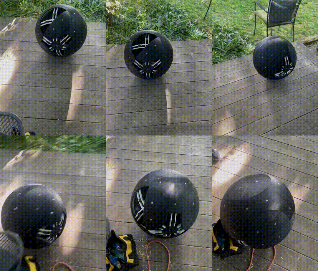
With my prototype complete and basic testing out of the way, I was able to collaborate with some friends over Spring Break to get it moving. The goal was to program it to operate better, with smoother movement and reliable behavior. Accelerating and slowing the ball needed to be done gradualy using feedback from the on board sensors to prevent the mass from completly flipping around the center.
The first tests resulted in unpredictable movement forward and backward. Jittering and wobbling was common without tuning and the motor had so much speed and torque that it could spin around the axel in place causing it to just vibrate. We made adjustments to the code and added a PID loop to allow for smooth acceleration and deceleration. Deploying it on a field we found that the ball had better turning than expected given the small counter weight relative to the total mass.
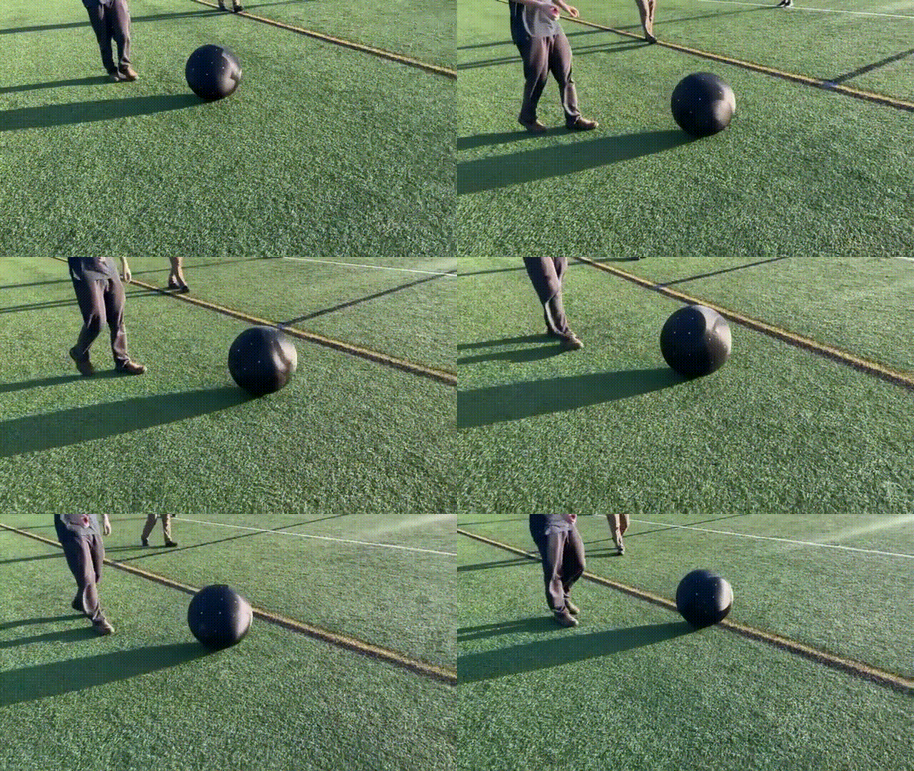
Overall, this prototype was a huge success. On our third test drive it rolled off a curb and shattered the acrylic subframe that supports the ball under its own weight. I am excited to move forward with a more refined version of the robot in the future. Utilizing this experience, I plan on adding the head to the next revision along with changes to the frame and layout of the robot.
MISO Data Logger
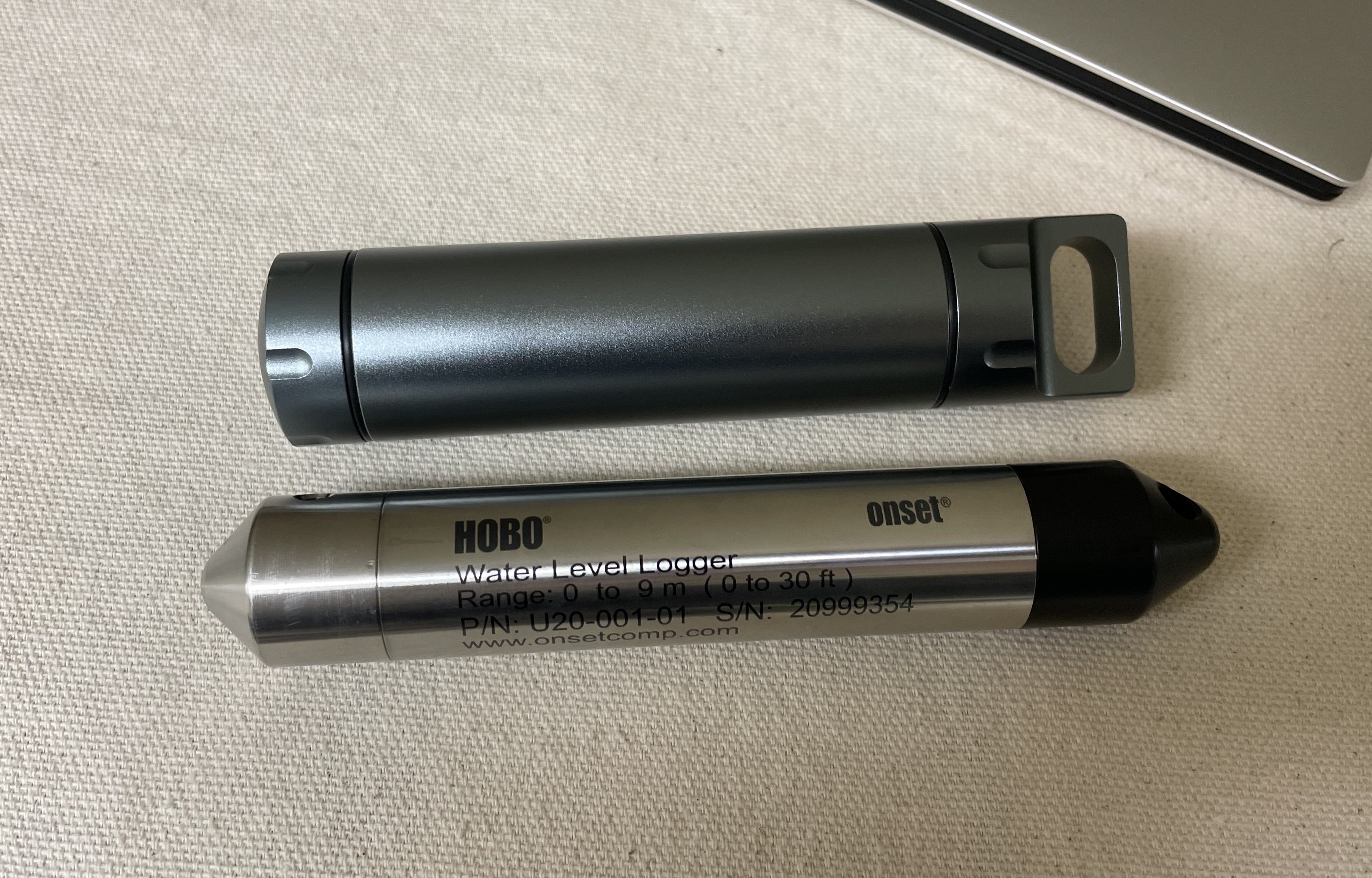
The goal of the MISO Data Logger was to create a product comparable to industrial underwater sensors while making the sensors modular. The modular I2C Sensor Cap is interchangeable with any I2C capable sensor setup. The MISO logger is equipped with an I2C sensor Input, Real Time Clock (RTC), MicroSD card for config and data storage, magnetic interrupts, and is powered with a standard 18650 battery for easy maintenance.
Keyboards
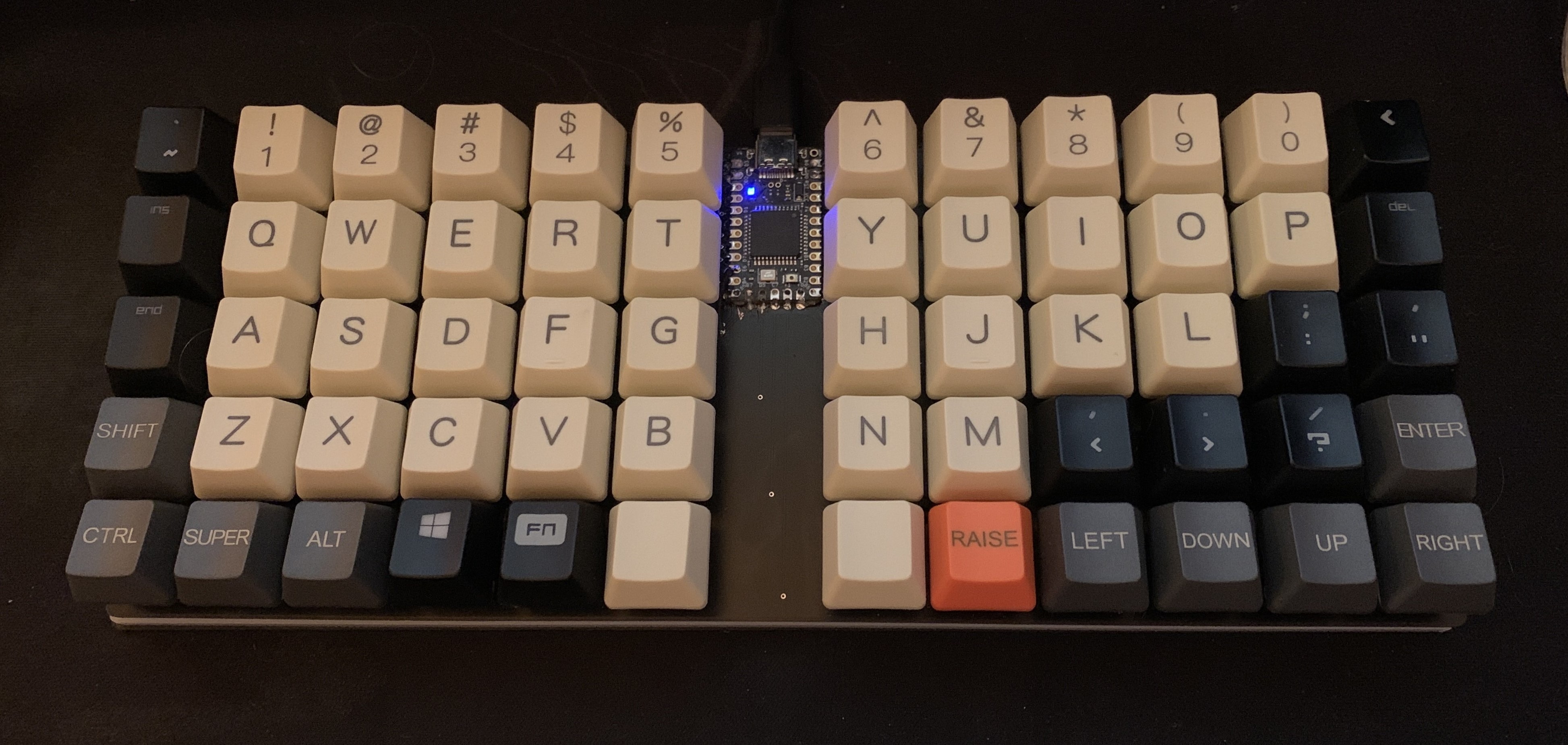
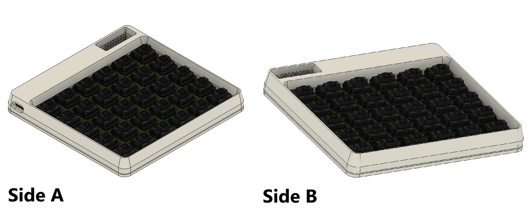
While exploring options for a replacement keyboard and not finding anything I liked, I chose to design my own keyboard. To create a keyboard that would work best for me. To date, I have designed two keyboards: the Berm and the Split. The Berm is a 65% low profile ortholinear keyboard with separated halves. The Split takes everything I liked about the Berm to the extreme. The Split Lowered the keys by 10mm (from 25mm), added a proper enclosure, and fully split the keyboard in half. With the goal of making a base PCB that is identical for both halves of the keyboard. With it being a left or right half based on which components are populated.
OPEnS Lab Research
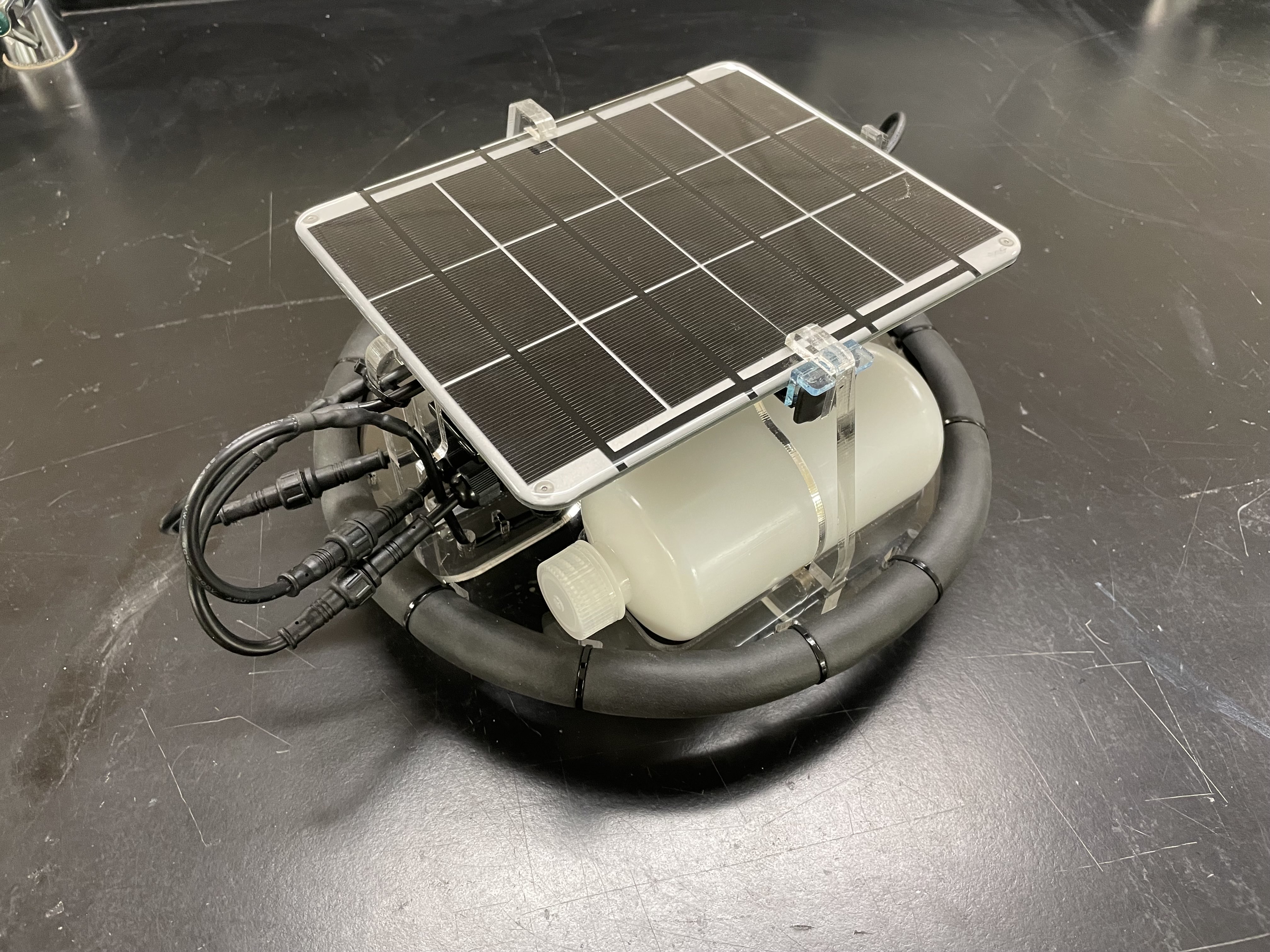
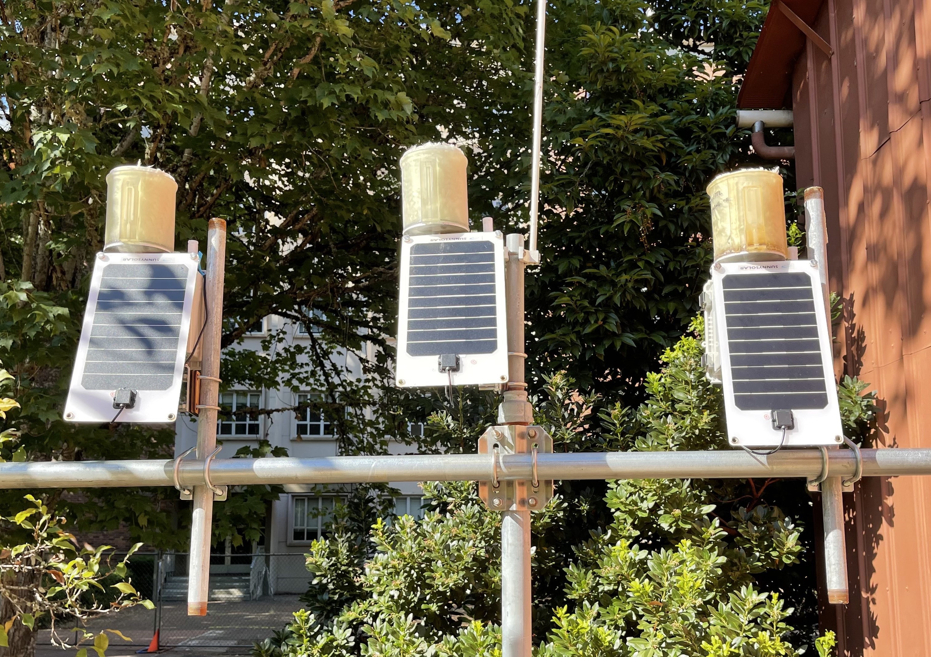
While working at Oregon State University's OPEnS lab, I learned about environmental sensing. I led the SmartRock and Lilypad Projects and assisted Evaporometer, WeatherChimes, RainSavor, and Isotopic Sampler.
First Robotics
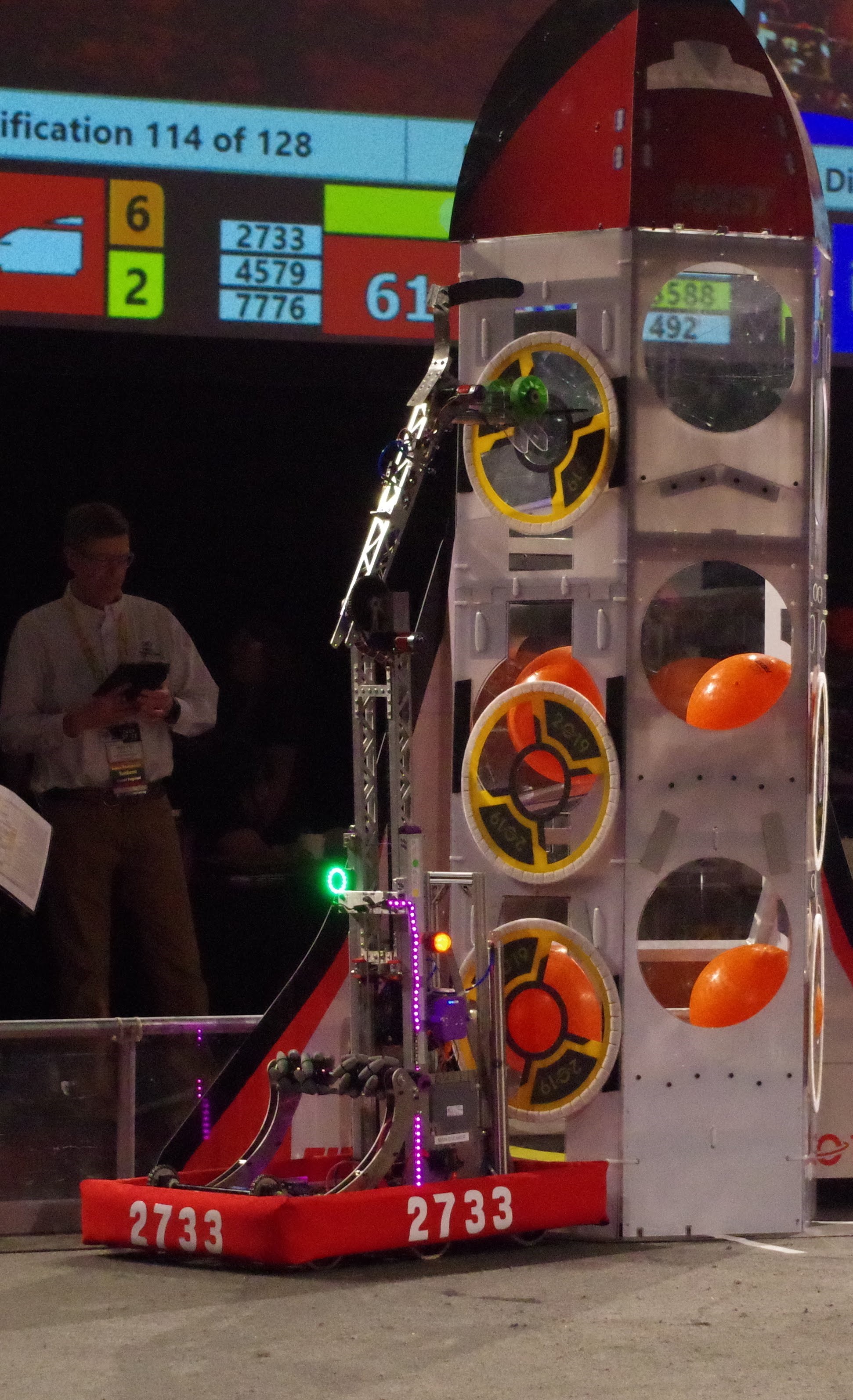
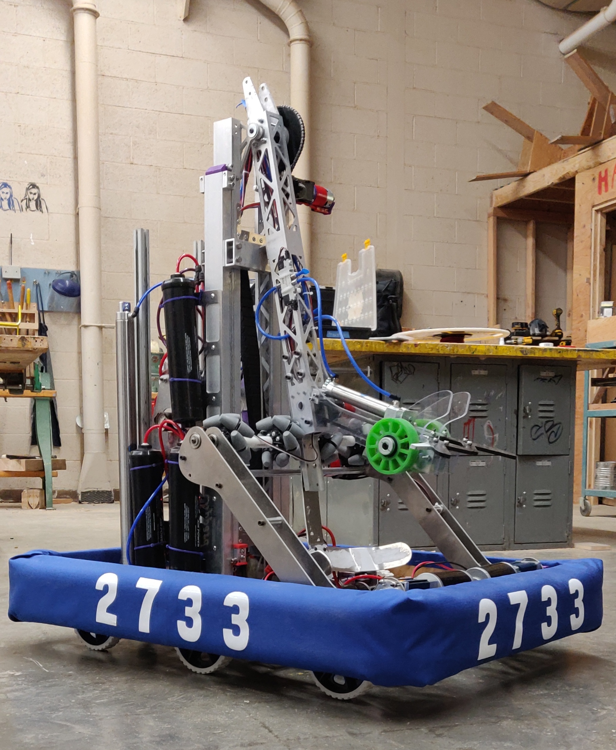
I was on the Pigmice robotics team and competed in the FIRST Robotics Competition (FRC) all four years of high school. I led the CAD of the robot all four years and was Design Captain for my Junior and Senior Year.
Instructable
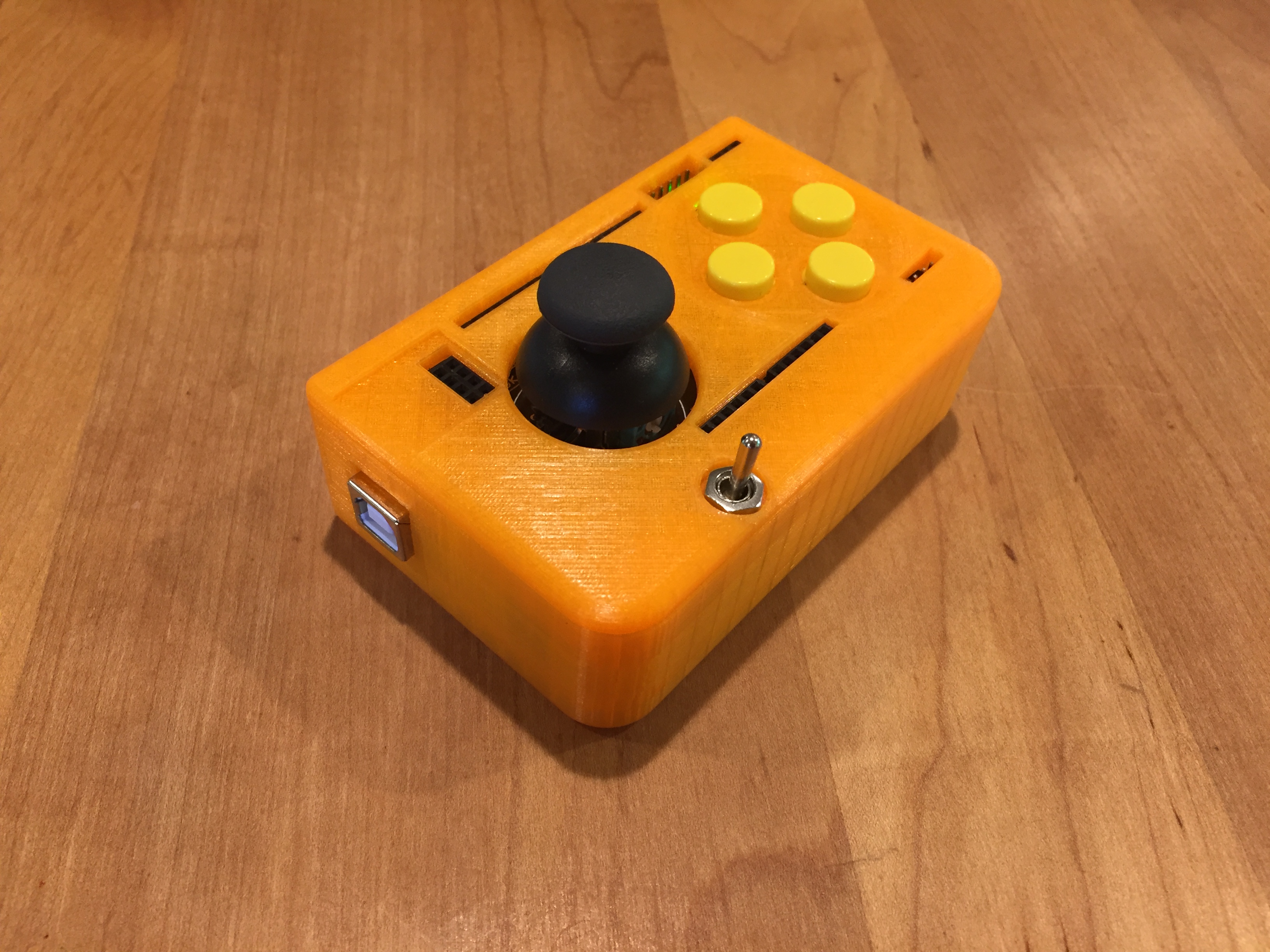
This is a controller I designed for any Arduino project that needs remote operation. It can connect using RF, nRF, Bluetooth, and more. It is compatible with a display if needed and runs on an internal 9V battery.
